- Hits: 92721
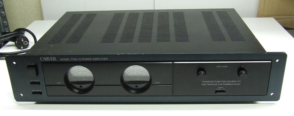
The Carver TFM-15 Power Amplifier is one of the most well-known amplifiers designed by Bob Carver, president of Carver Corporation. As Bob Carver say, TFM-15 is capable of high simultaneous current and voltage output.
Judged against conventional amplifier standars, it is second to none; its soud quality is smooth, sweet and absolutely dynamically accurate. It can deliver more than 100 watts RMS per channel into an 8 ohm loudspeaker with les then 0,1% THD and even more power into lower impedances. In addition, the closed-loop frequency response extends from below 10Hz to beyond 100kHz.
The TFM-15 Power Amplifier shares many of the sonic characteristics of Silver Seven Tube amplifier, including extended low frequency performance, excellent power bandwidth, low residual noise, stable performance into complex impedances, flat frequency response, low distorsion and hight dynamic headroom.
Features:
- power: 100W per channel into 8 ohms, 140W into 4 ohms and 200W dynamic power into 2 ohms
- distortion: THD < 0.1% from 20Hz to 20kHz
- noise: 110dB A-weighted referenced to rated power
- gain: 31dB with input level controls fully clockwise
- input impedance: 30k ohms
- weight: 17.2 lbs, 7.8 kgs
Though the Carver TFM-15 is globally well projected amplifier, it has some little flaws.
Circuit analysis
This amplifier employs a single input stage differential pair configuration with a simple tail resistor connected to a fixed voltage circuit regulator equiped by Q701 and the zener-diode D701. This configuration is as simple as possible but it has poor CMRR and PSRR.
The VAS stage has a push-pull configuration.
The output stage consists of two sets of 2 parallel transistors operated as emitter followers, driven by another pair of emitter followers. The output transistors have 0,33 ohm ballast resistors to ensure current sharing and bias stability.
General flaws:
- wrong sizing of main power supply electrolitic capacitors
- heatsink for VAS transistors can be increased
- short life for negative feedback electrolitics capacitors
UPGRADES
In this article I will illustrate how to make a total restoration of this amplifier with some little upgrades to improve sound quality and general stability.
Main power supply
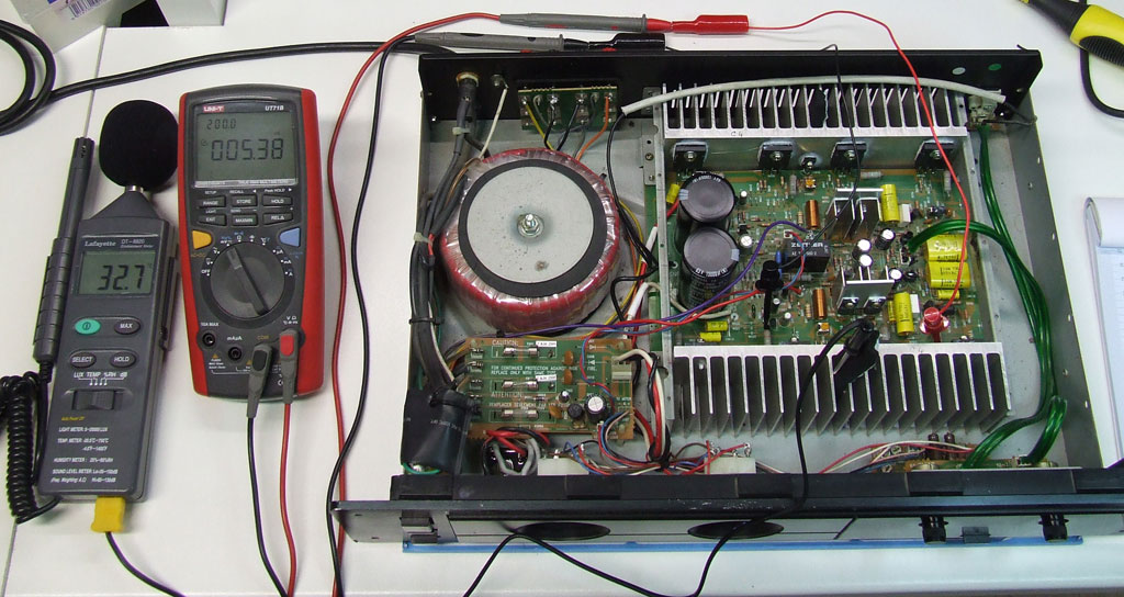
The Carver TFM-15 has a good power supply with a toroidal transformer, 4x 6A rectifier diodes and 2x 15000uF 50V capacitors. I have changed the original 4x 6A rectifier diodes with a 25A KBP2504 bridge rectifier. Original capacitors are rated to 50V but I have measured a real voltage of 53V, in fact the old capacitors were blown. I have changed them with two new snap-in Nippon Chemicon 15000uF 63V 85°C 35x63mm but you can use other types.
|
List of changes |
|||
|
Description |
Quantity |
Original Parts |
New parts |
|
D007 - D010 |
4 |
6A 400V |
|
|
|
1 |
|
25A KBP2504 bridge rectifier |
|
C001, C002 |
2 |
15000uF 50V elec. |
15000uF 63V elec. |
Input stage
The transistors used for the input stage and for the VAS stage are good but for a complete restoration you have to change its all with a new. I have changed all transistors with new same types.
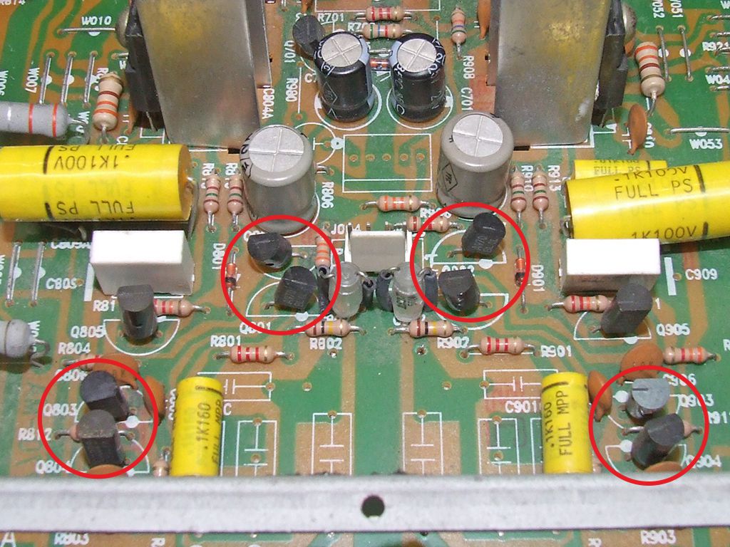
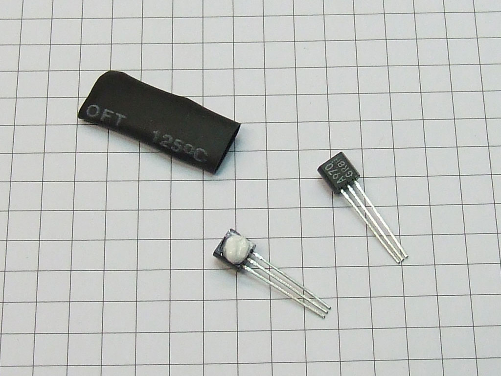
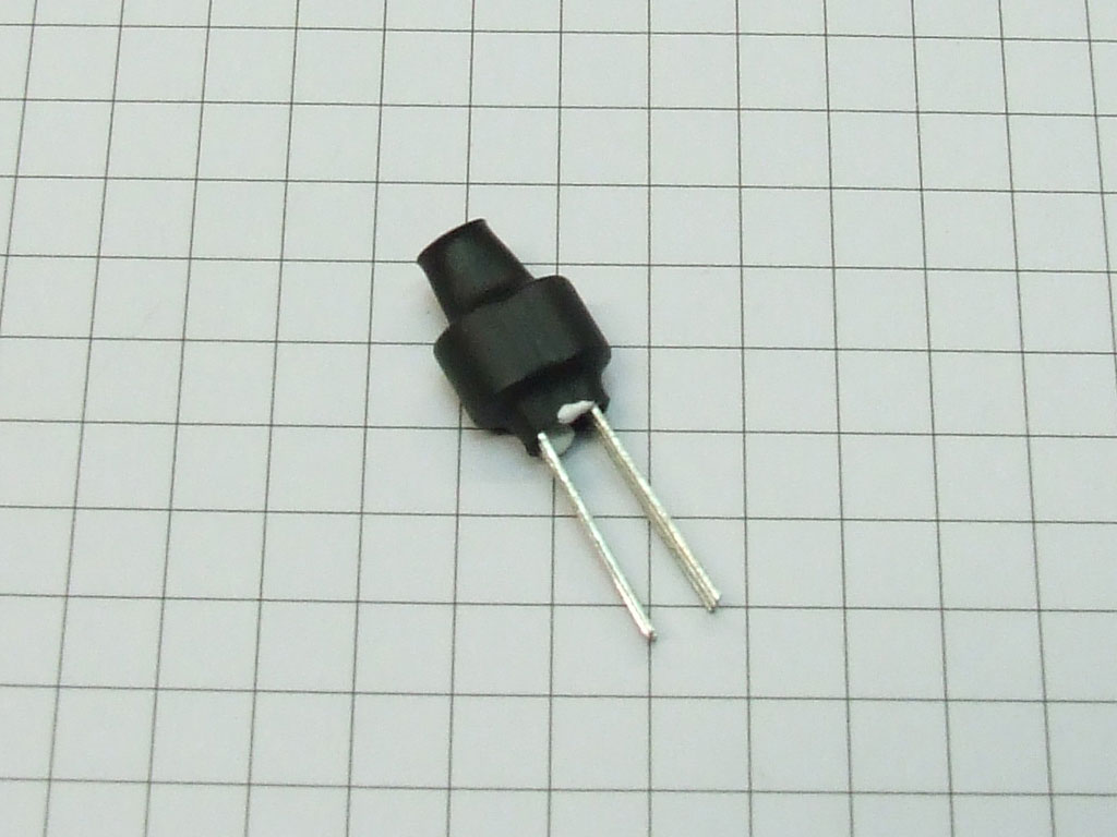
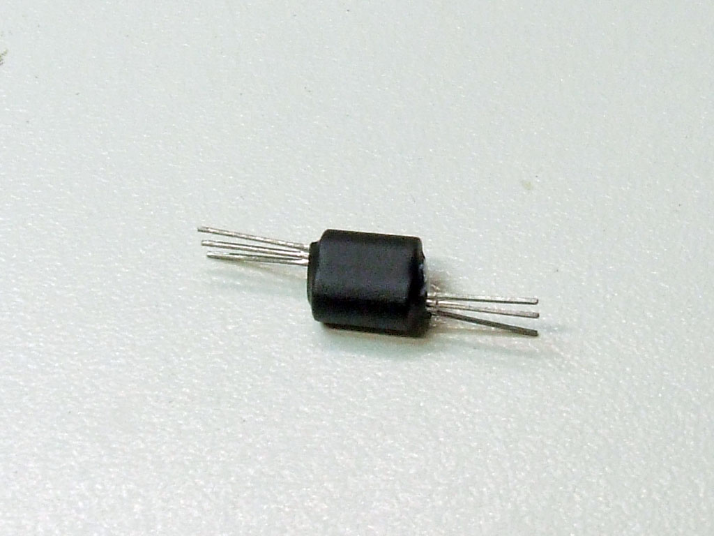
To increase linearity of the input stage I have thermal coupled the differential pair transistors. I have coupled face to face the TO92 transistor with a thermal grease and I have fixed its with a heat shrink tubing as you can see in the figure below. I have thermal coupled Q801 with Q802, Q901-Q902, Q803-Q807, Q903-Q907.
For better power supply filtering on the constant voltage circuit regulator equiped by Q701 and the zener-diode D701 I have changed the old 220uF 25V capacitors with new 330uF 35V + 100nF 63V. I have changed the 22V zener diode D701 with a new one.
|
List of changes |
|||
|
Description |
Quantity |
Original Parts |
New parts |
|
C701, C702 |
2 |
220uF 25V elec. |
330uF 35V elec. + 100nF 63V polyester |
VAS stage
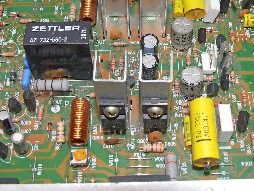
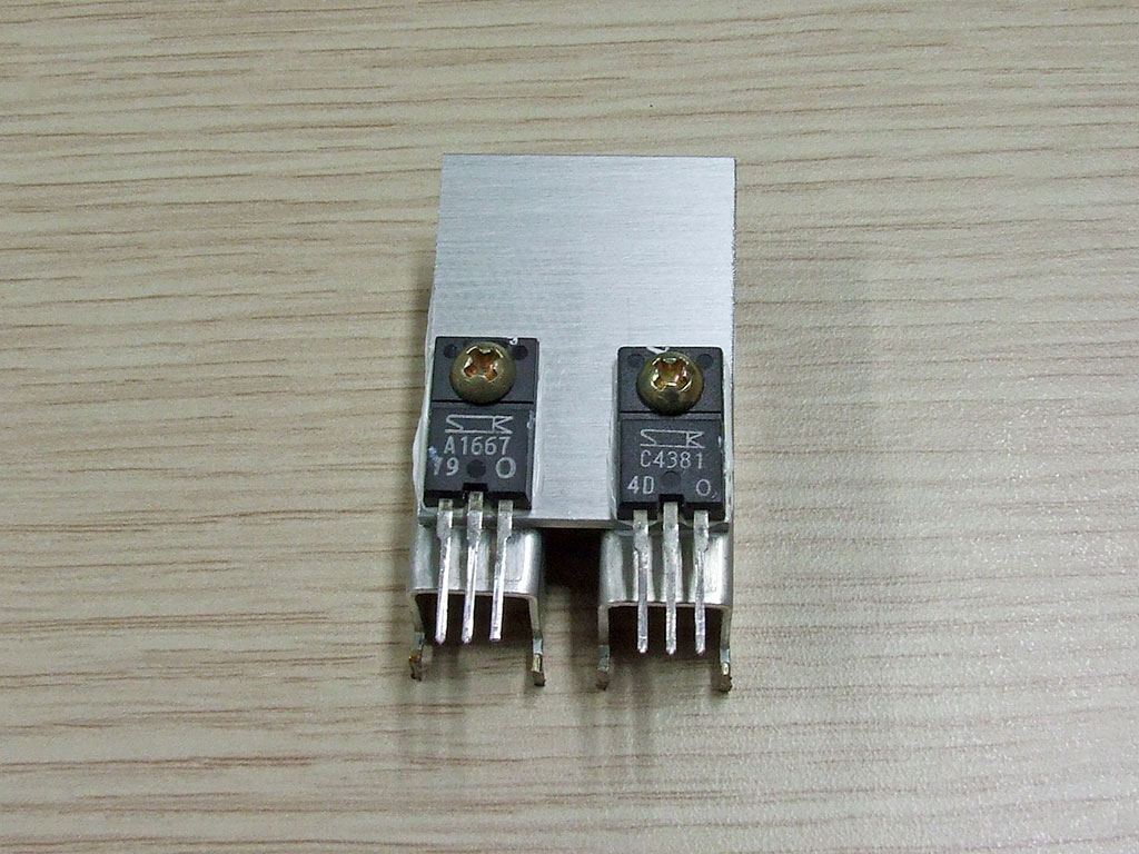
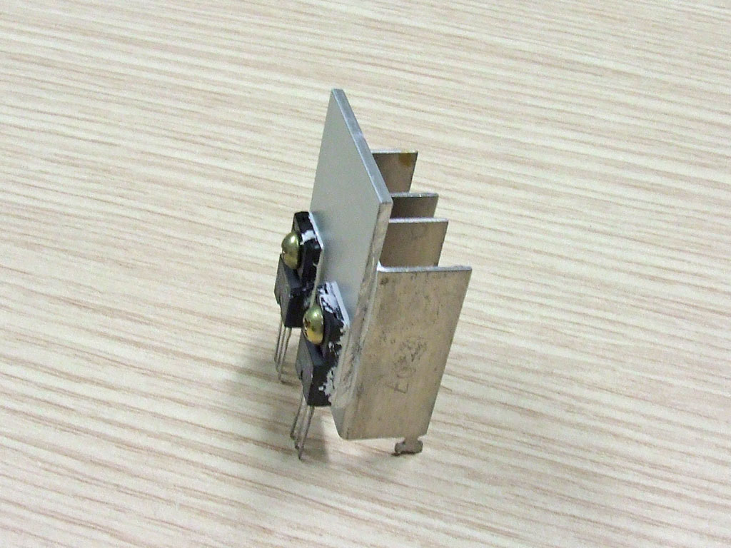
I have changed the VAS transistors with new and I have increased the heatsinks with a piece of aluminium. The VAS transistors in my amplifier are 2SC4381 for Q807, Q907 and 2SA1667 for Q808, Q908.
Negative Feedback Network
When I have examined the capacitors C804 and C904 of my amplifier, I have measured them and I have noted that were fault. I think that these capacitors are too close to VAS transistor heatsinks and have low life expectancy. I have changed them with a new same type capacitors and I have added a 2,2nF 1kV ceramic capacitors for increase filter performance at high frequency. For best sound improvement you can replace C805 and C905 30pF ceramic capacitors with a new silverred mica type. You can replace all Miller compensation capacitors with a new silvered mica type (C806, C807, C808, C810 and C906, C907, C908, C910).
|
List of changes |
|||
|
Description |
Quantity |
Original Parts |
New parts |
|
C804, C904 |
2 |
220uF 16V elec. NP |
220uF 16V elec. NP + 2,2nF 1kV ceramic |
New components on output stage
I have changed all transistors with new more performant types. I have replaced all old transistors with new On-Semi matched pair transistors. The new transistors have much more Safe Operating Area and more current capability, this improves the capacity of drive difficult loads and increases the stability at high temperature.
|
List of changes |
|||
|
Description |
Quantity |
Original Parts |
New parts |
|
Q809, Q809A, Q909, Q909A (output stage NPN transistors) |
4 |
2SC3519 |
|
|
Q810, Q810A, Q910, Q910A (output stage PNP transistors) |
4 | 2SA1386 | MJL21193 |
Bias regulation
First of all you have to check with a DC voltmeter the voltage on speaker terminals, you must have less then +/- 20mV. You have to regulate the BIAS as described at page 4 of service manual.
Other mods
I have removed the original vumeter lamp and I have installed 2 blu leds instead.
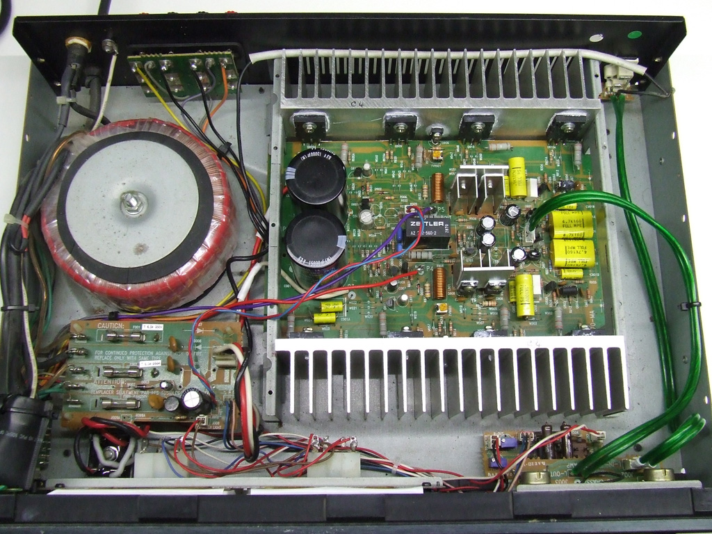
Photo after the upgrades
Our Services
We offer repair/restore/upgrade services, please contact us to get a quote.